Tag Archives: Synthesizer

Vintage KORG MS-20 repair and the “bad copy” service manual errors

My poor synth was diagnosed as dead and no longer “resurrectable” (yes, resurrection is not that uncommon with electronic equipment), several years ago, already.
On the last visit by my former audio technician, the response was:
“Buy yourself a new Behringer clone, they’re not too expensive ..”


No, I couldn’t accept that my first synth was destined to be thrown away! Apart the economic side, there is another aspect that always makes me think: The old keyboards are a piece of our history, witnesses of our technological evolution and often rare survivors of other times, but not for these reasons, musically outdated. Indeed, like important art objects, they should be protected by special laws! :D

OK, joking aside, on those times, my technical knowledge in electronics was not sufficient to being able to make a diagnosis and schematics, looked to me like hieroglyphs of some alien race.


But with patience, reading texts, watching videos and consulting friends, I started to become more aware on how my old and stinky electronic musical instruments work, even inside their panels.


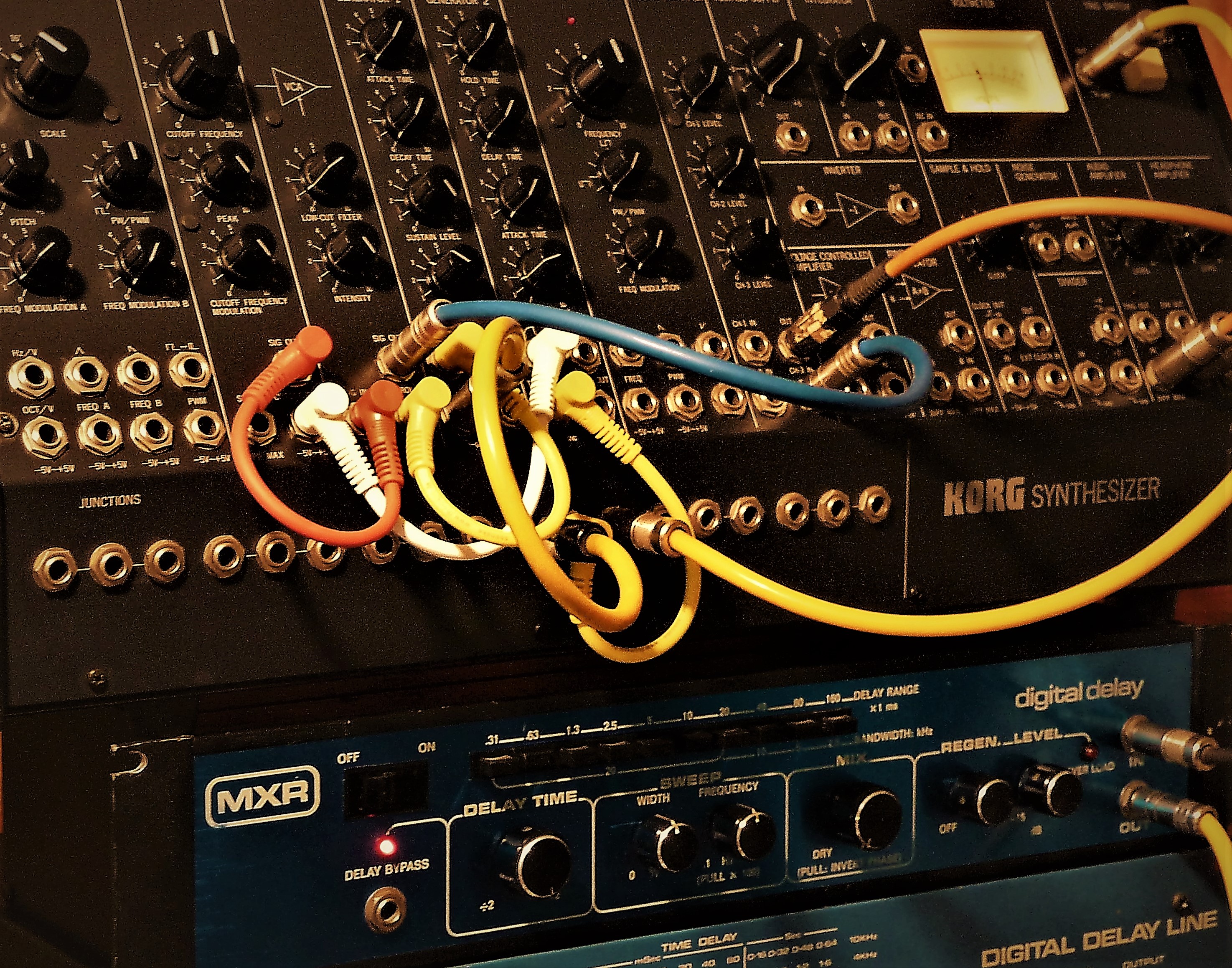
My synth remained open in a corner of the studio for very long, I walked past it without even seeing it, almost to avoid the pain of having to give up, but one day everything changed: I looked at it carefully and whispered “don’t worry my friend, we’ll be back playing together, like in the old days, very soon!” … Well, to tell you the truth, it wasn’t very soon really, but the promise was becoming true. The KORG MS-20 started always being on my mind and I was looking for information and literature to prepare myself to the repair.


It took a couple of weeks to “unravel the problem”, check what the hell was wrong with it and try to figure out why the previous attempts had failed.
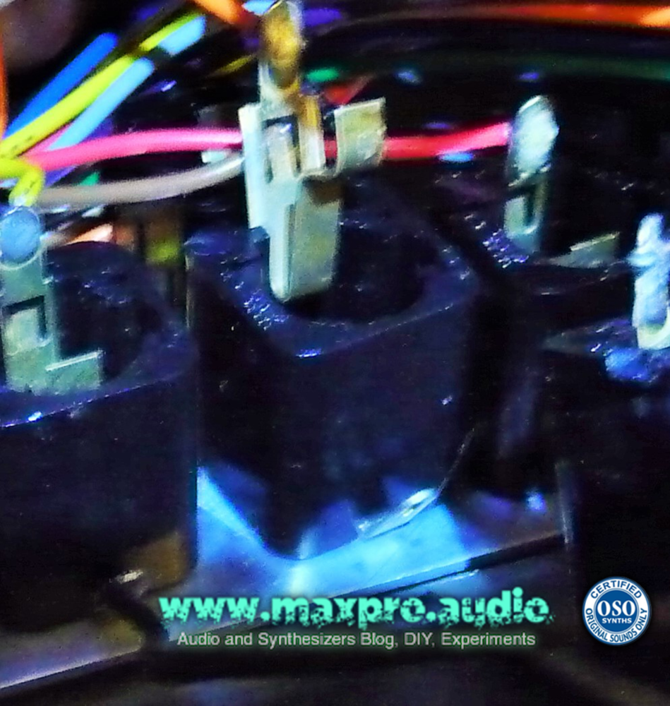
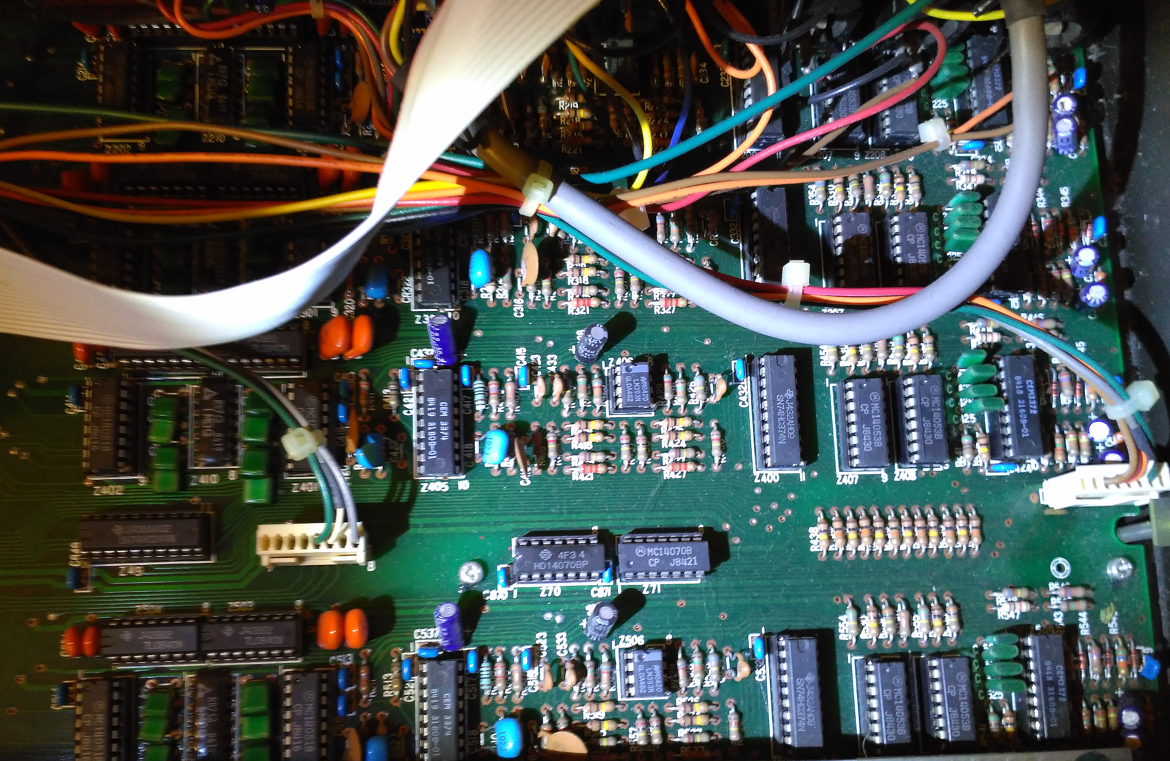
Lacking power to one of the rails, I imagined there was a problem in the power source, but the fact that the technician hadn’t success, made me waste lots of time “looking” around. Eventually, to my horror, I discovered that the culprit for the inability to repair the synth was the technical manual, which unexpectedly contained an error!
Yes, I understand that it seems impossible, but it is like this: The “sacred text”, obligated reading and time saver of every technician, seems like impossible it has not been studied in detail and made “perfect” … I could not believe my eyes!


The reason is that, the only technical manual available on the internet about the synth KORG MS-20, it had a strange “BAD COPY” stamped on the cover, but having been misprinted, I thought the warning was related to this aspect. Who would have thought that BAD was SO BAD! : D
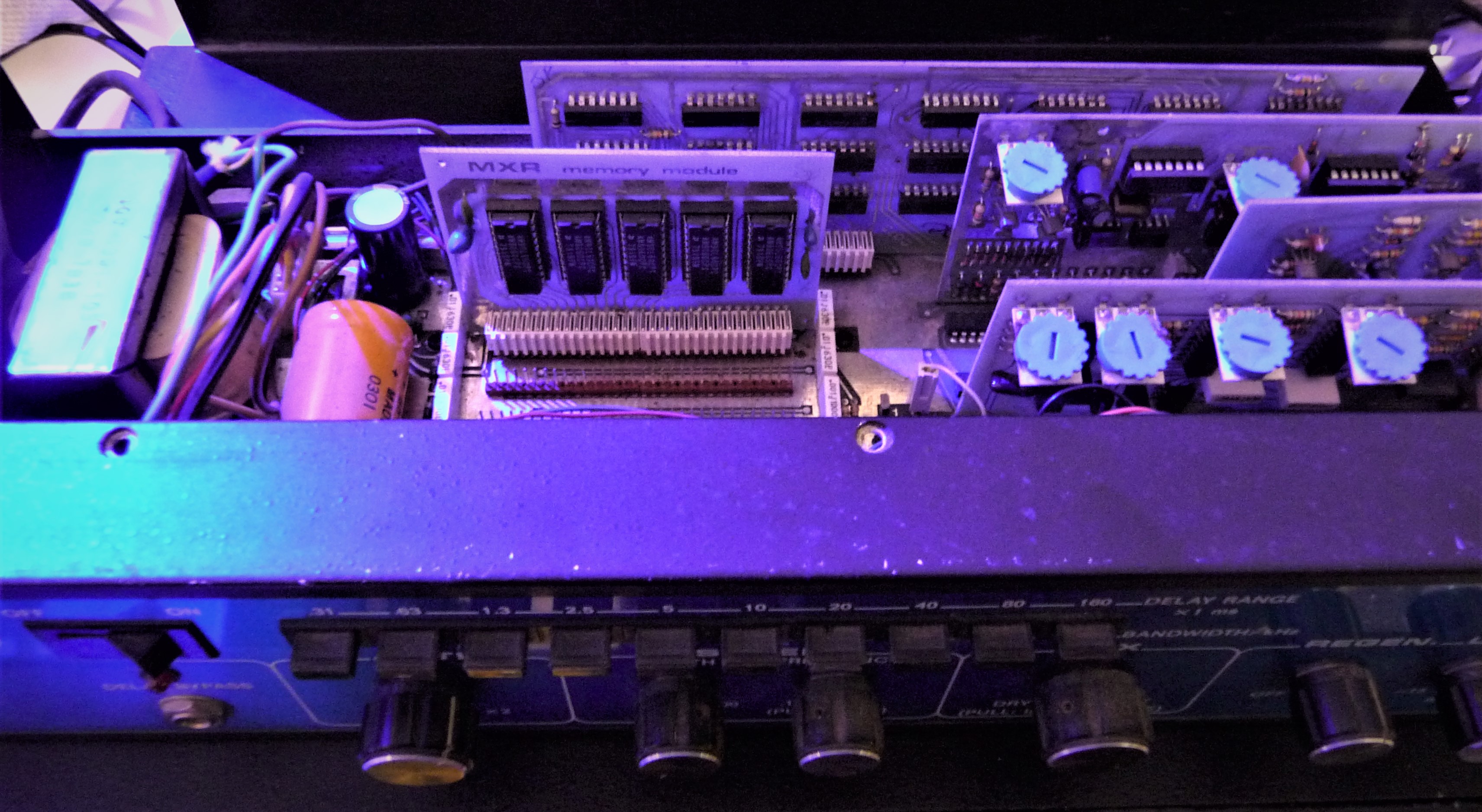
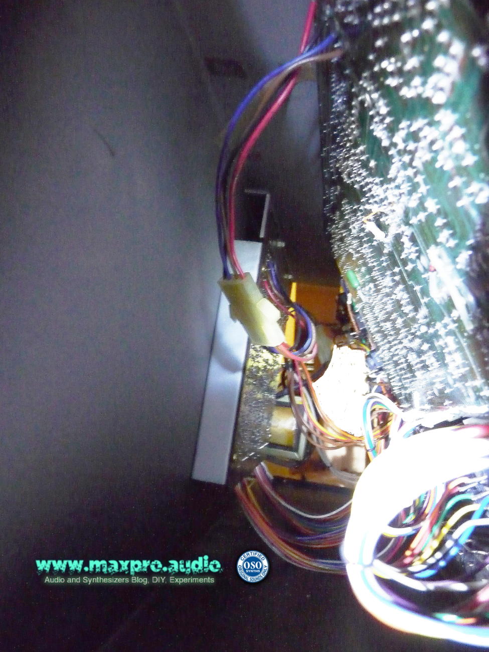
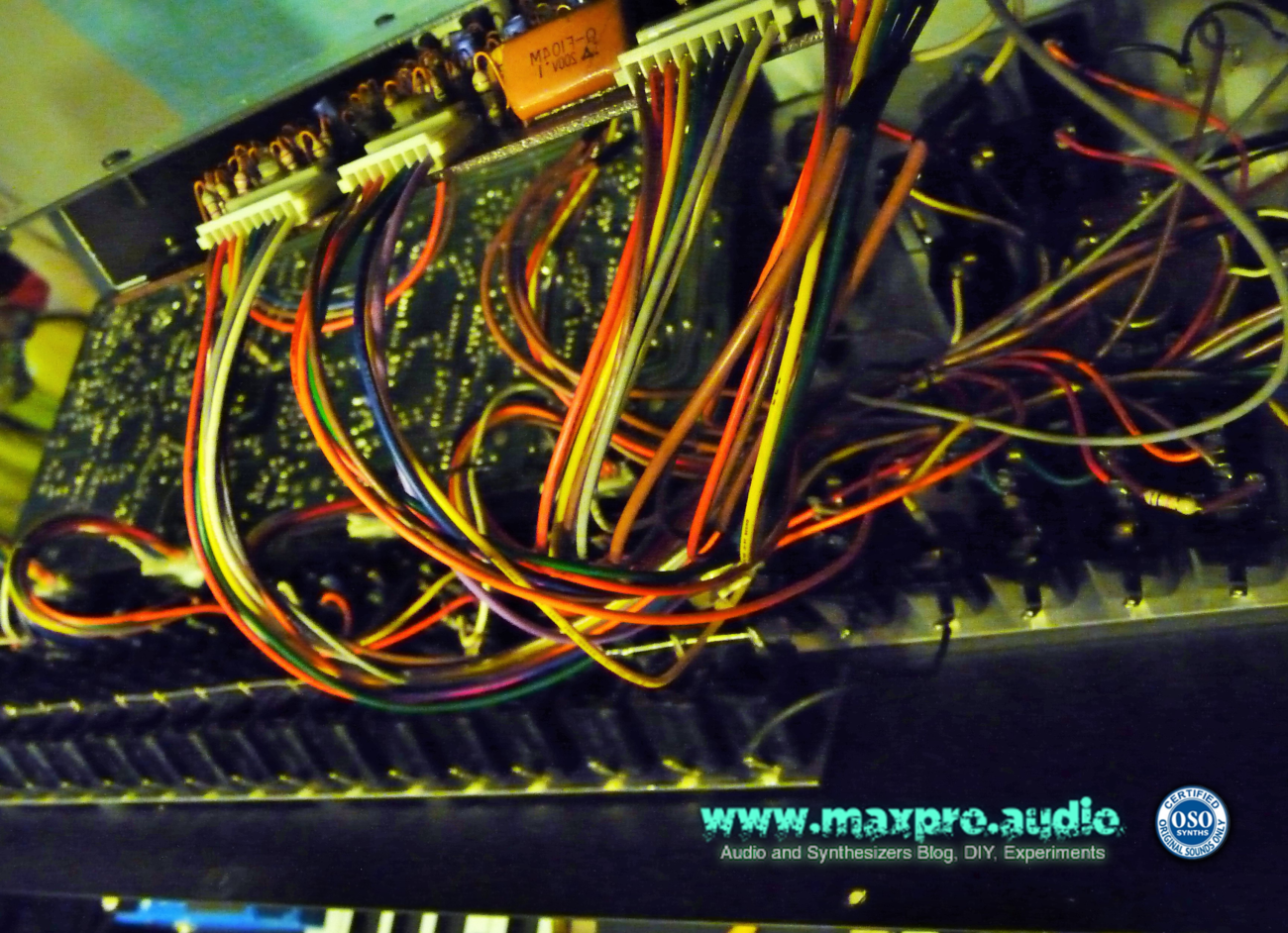
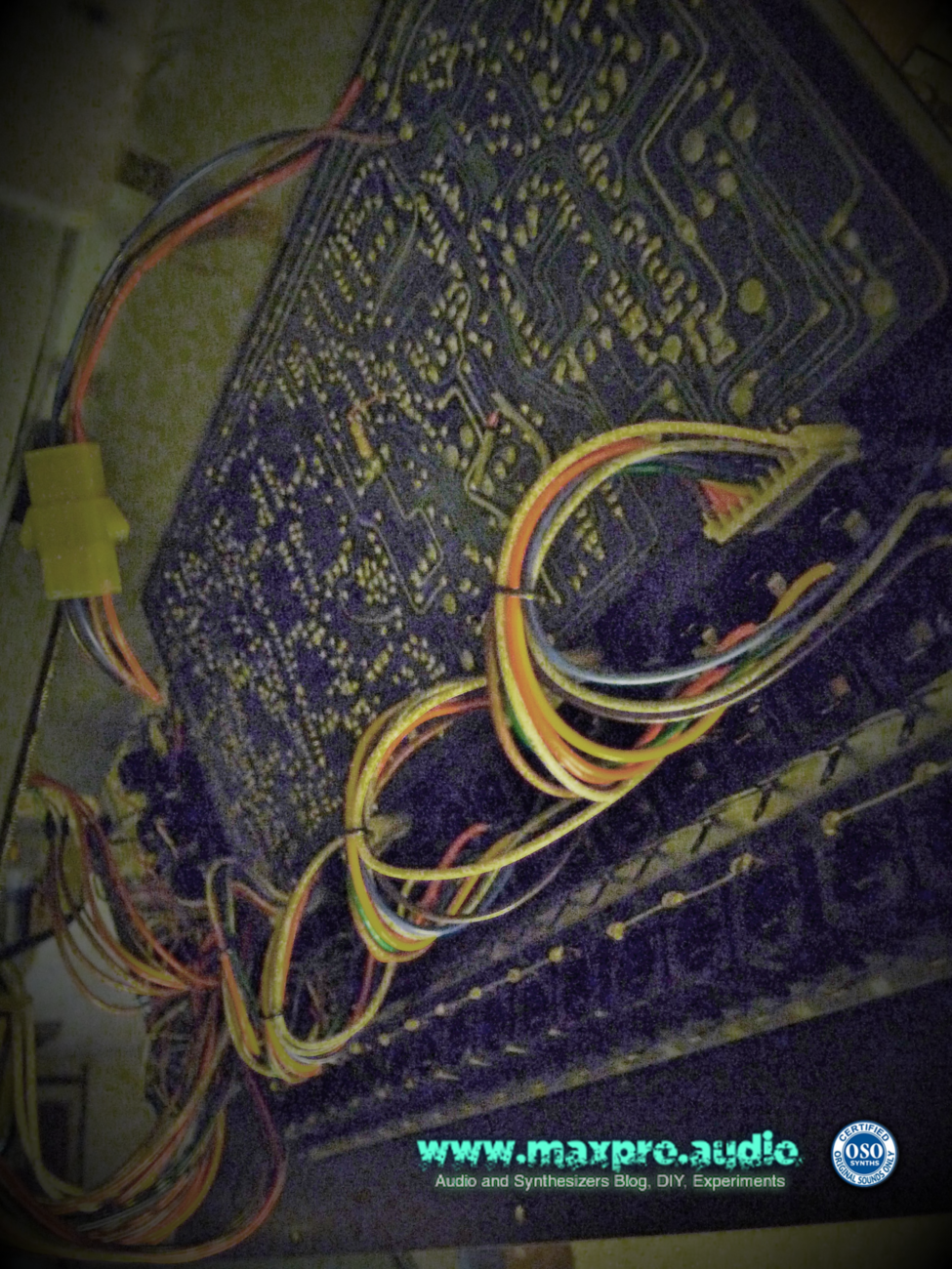
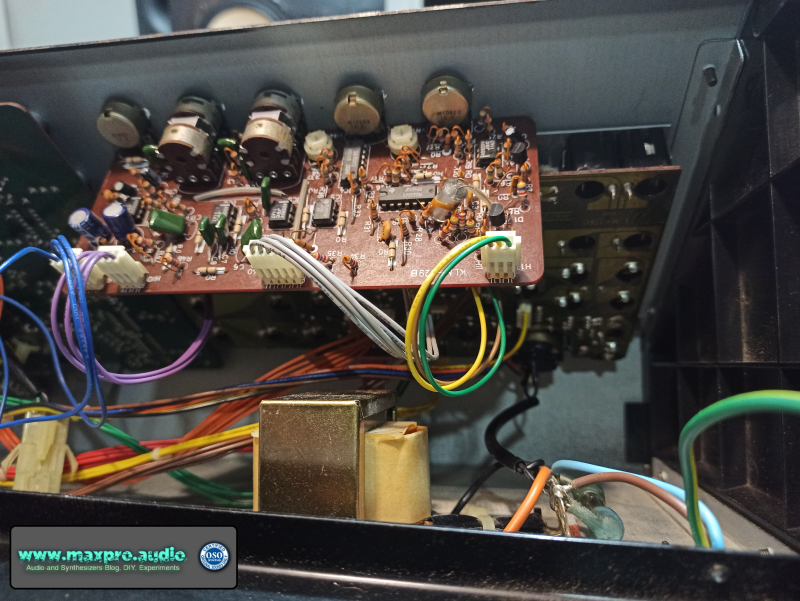
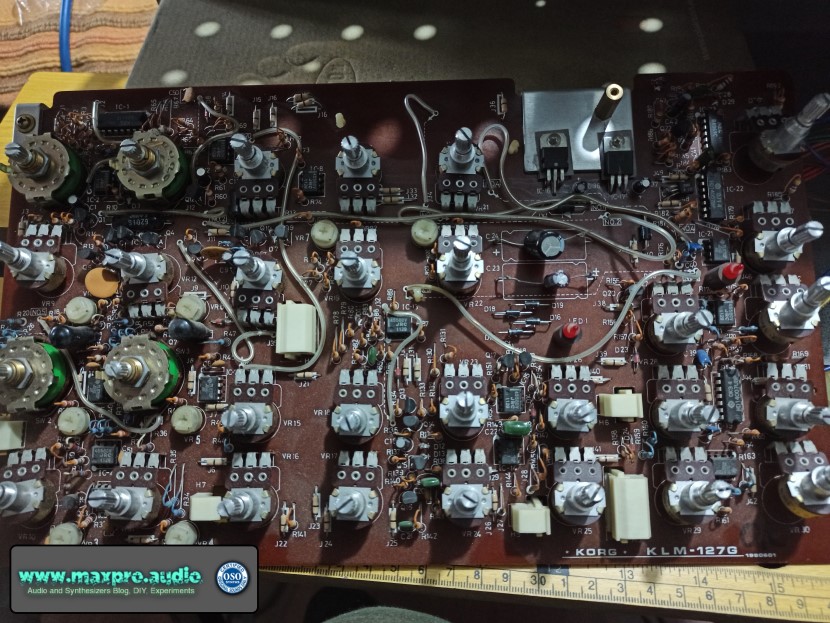
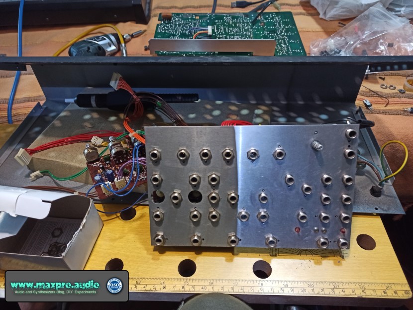
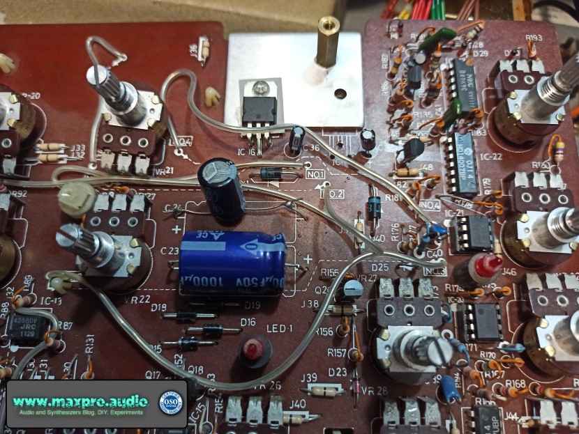
Usually, a technical manual has a “layout” with the graphics of the components mounted on the board, with their relative values, a list of the installed components and the technical diagrams with the paths of the tracks and the symbol of the components. In this case, in the layout, the two voltage regulators were reversed and without a thorough study of the scheme, comparing the tracks with the real ones, the diagnosis would have been that of my technician, “non-repairable synth“.


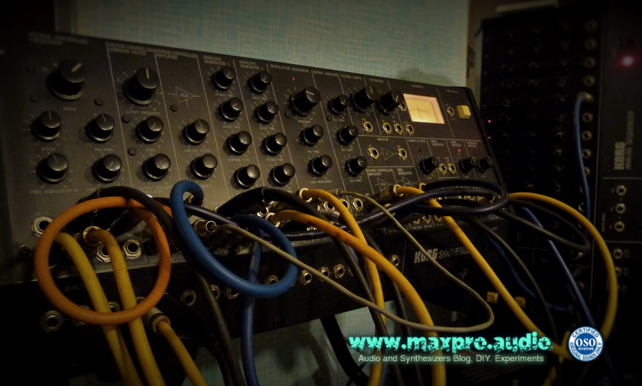
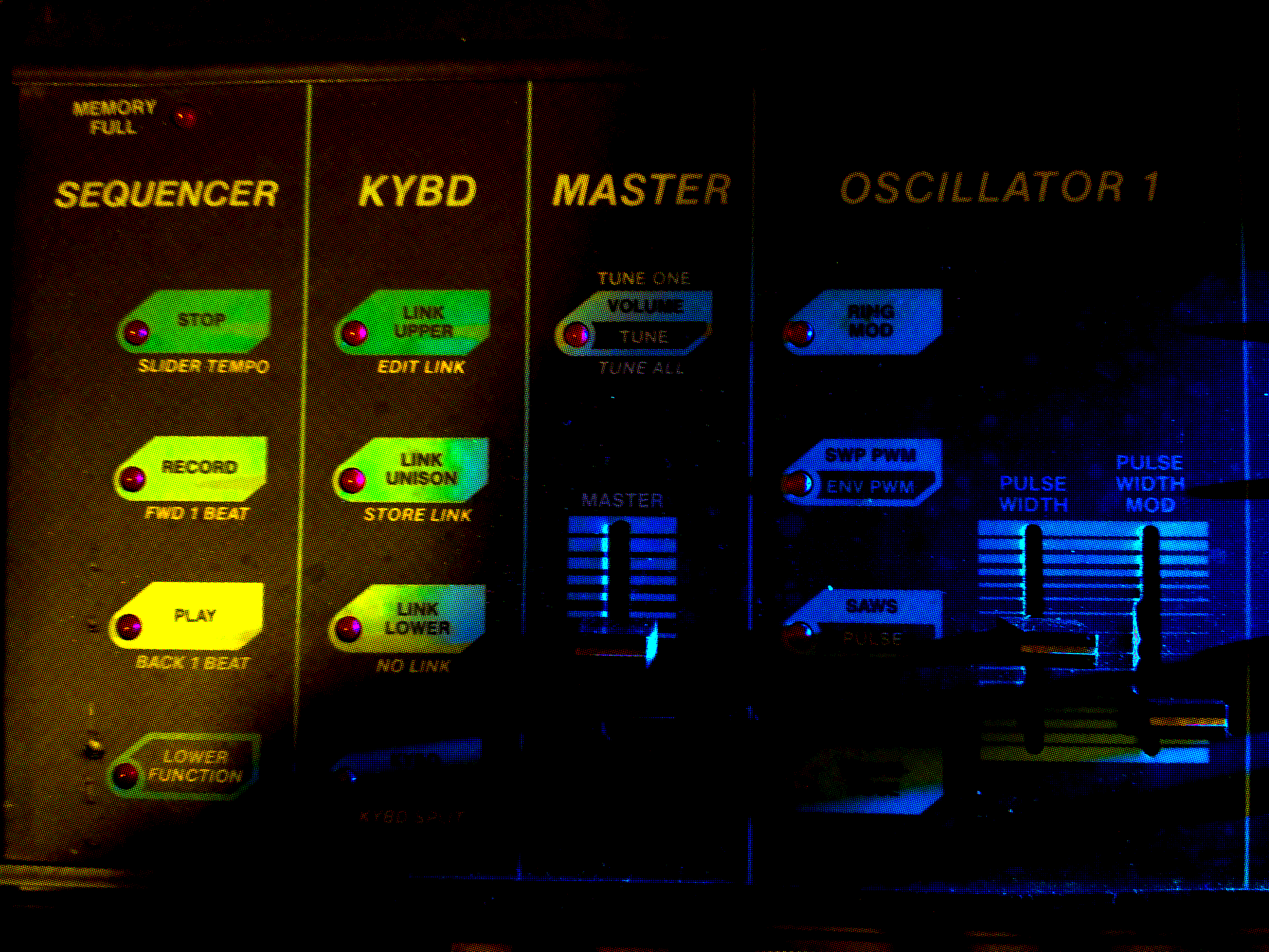
Once the trick was discovered, it took a few minutes to “resurrect” the synth. You cannot imagine the happiness of seeing the mini-LED of the LFO flash again, to remain still in a metaphysical environment, “after the long death!”

(2021 Massimo Belladonna – maxpro.audio)

CRUMAR Spirit, vintage analog synth repair

It has been hard to find the time to write, this time!
I’m starting producing videos related to this blog and as my knowledge in video editing is absolutely basic, this means long preparation times. Lots of things to learn so most of the time usually dedicated to music had to be diverted in watching instructional videos.

Finally, after too long, I decided to turn the Crumar Spirit, a first 80s monophonic analog synthesizer, back on to check if it was still working, given that last time it had shown signs of “tiredness”.
While recording a video, I realized that something strange was going on. Sudden jumps in intonation, notes that didn’t want to play, or that sounded intermittent.. then suddenly the worst! The keyboard started emitting only the note pulses (Gate) and no longer the pitch. (CV)
..and so once again, abrupt split to the opposite cerebral hemisphere and here I am again to repair “in the field” my junk!
Inspecting the interior of the Crumar Spirit, the first suspect was certainly the Input/Output board, where the CV/Gate data enters and leaves the synth. And in fact, the culpable was found there! At the height of the connector, a track of the circuit was broken, perhaps due to the action of the connected plugs, over the years.
With a simple bridge, I was able to repair the circuit and bring back into the Spirit, its spirit!

The Art of Procrastination, MXR M-113 Digital Delay


The MXR M-113 Digital Delay has been one of the most popular first generation audio delays, as it had a good quality but was more affordable than the previous processors. Introduced in ’76 at around 1000 USD, it was still expensive, but a lot less than the other digital delays available in the market.

MXR was specialized in guitar pedals, this delay was instead offered in a 19″ rack unit and, same as the other effects of the professional rack series, (Flanger/Doubler, Graphic EQ, Pitch Transposer) became very popular and used by famous artists such as David Gilmour, Frank Zappa, Roger Waters, Brian May and Mike Rutherford.

Modular

MXR memory module

To contain costs, a modular architecture was chosen. Optional memory boards were inserted in slots, to increase the delay time, but these were pretty expensive, costing almost like a complete unit.

MXR Digital Delay Internal Cards


Digital noise..well not only that! :D

Unfortunately the M-113 Digital Delay, same as its collegues of the same period, is pretty noisy and not only referring to the actual standards. Apart digital noises always present, these processors have a marcated tendency to generate audio hum.

The Model 113, Digital Delay has a maximum bandwidth of 20KHz, but this decreases with longer delays, down to 2.5KHz. The longer the time between repetitions, the tighter the passing frequency band, being reduced through antialiasing filters (HPF and LPF) the more the delay time is increased.


MXR Digital Delay Test Drive

As there are several video examples already of this delay tested on guitar, I thought it could have been a good idea to try it, using some unusual but hopefully interesting sounds.
To record, I used a dbx DI box and the signal sent to a Universal Audio 610 tube preamp, even taking all possible counter-measures, still a bit of hum is audible.

On the examples below, I feeded as sound source, a sweep from the filters in feedback of an old Korg MS-50 synthesizer, some piano chords I had recorded from a real piano and a couple of seconds of an oldschool reggae classic.

MXR Digital Delay, Test-01, (MS-50 Filter Sweep)

01) Dry sound, straight from the MS-50.
02) Delay Range 160ms, Delay Time x2, 50% mix and maximum regen (feedback)
03) Delay Range 160ms, Delay Time 0, 50% mix and maximum regen (feedback)
04) Delay Range 160ms, Delay Time 1/2, 50% mix and maximum regen (feedback)
05) Delay Range 160ms, Delay Time Sweep 01 (moving the Delay Time knob)
06) Delay Range 160ms, Delay Time Sweep 02 (moving the Delay Time knob)

MXR Digital Delay, Test-02 (Piano)

I chose these piano chords I recorded as, having long decays, are ideal to test the effect of short repetitions, when modulated. The effects space from phasing to complete madness. The last one is a strong modulation at the higher band of frequency of the sweep, reminding the effect of a ring modulation.

1) Dry Piano
2) Delay Range 1.3ms, 50% mix
3) Delay Range 10ms, 50% mix
4) Delay Range 160ms, 50% + Mod
5) Max Frequency Mod


MXR Digital Delay, Test-03 (Rhythmic Loop)

On the following examples, let’s try something that really impressed me first time I played with a Powertran  (An article on it, is coming soon). On the MXR the feedback has a faster decay and there’s not the “freeze” function, but the effect it is interesting, too.  Once the delay is at tempo with a rhythmic pattern, having adjusted the decay time knob, all Delay Range buttons create a different version of the pattern, but on different speeds. Being the buttons based on a double time sequence, all these are compatible in tempo. Let’s experiment with a small classic reggae riddim loop:

1) Dry loop
2) Loop effected as sort of Beat Repeater


MXR Digital Delay, Test-04 (MS-50 patch)

Last example, this time using a more complex sound from the MS-50.
1) Dry MS-50 sound
2) MXR MS – 50%MIX, 75% Feedback
3) MXR MS – 50%MIX, 75% Feedback + Mod
4) MXR MS – 50%MIX, 75% Feedback + Fast Mod

Service Manual: https://app.box.com/s/4t78o8xtzd


The Dark Side of Vintage Machines: Part 1 – Korg MS-50, failing jack connector repair and test drive

KORG MS-50 1979 Modular Analog Synth


Korg MS-50
Korg MS-50

For “The Dark Side”, I mean the real nightmare always lurking, while playing with vintage machines: Their tendency to break apart, often in the middle of an important session.

Always the best option, if possible,  is to be able to do some small fixes in “DIY mode”, to save money and have the repair done promptly. The older the machine, the easier the repair is, usually. This is valid, if some rare parts availability, doesn’t interfere in the logic.

Doing some tests recently,  I found that the auxiliary VCA section of my Korg MS-50, had one of its jacks broken inside. The plug was not kept in its place, like if there was nothing inside to retain it. I suspected the positive pole plate got broken.

Good occasion to open up the synth and look what’s inside ;)

As soon as I unscrewed and removed the later panels, I remained impressed by the fact that in the interior of its panels the Korg MS-50,..ehm…IT’S EMPTY! :D It’s pretty impressive how Japanese technology was advanced, considering that this synth was in production, since 1979.

Korg MS-50 Inside 01

In the interior of the Korg MS-50, there are just a couple of thin PCBs, plus the PSU board.

What occupy much place, are the plastic slots for the jacks metal connectors plates.

The only thing really modular to me,  is the placement of the jacks in the front panel, simulating the modules of a real modular synth. Modules can be connected through external connections only , same as a modular and not as the rest of the MS series, where some internal patching is placed already.

This not complete modularity, can look a bit suspicious by the most purists, but the sounds that this machine is capable to create are fantastic, even with it’s limited single oscillator configuration.

The Korg MS-50 have been pictured in Aphex Twin studio and should have been used by The Chemical Brothers.

REPAIR


Korg MS-50 Inside 02

Inspecting the interior, (with major relieve) I discovered wasn’t necessary to disassemble the whole synth, as removing the main PCB from the front plate, must be a really tedious process, considering all the jack bolts, to unscrew.

The cause of the fail for the broken jack, resulted in being the connector plate of the + polarity, that I found off its slot.


MS-50_int connector fail


Just some glue solved the problem, a much easier solution than what I thought was necessary, at the beginning.


TEST DRIVE


To test the VCA repair, I decided to make a demo, squeezing from the Korg MS-50 single oscillator, all its waveforms. I triggered them from its two Envelope Generators and a Korg SQ-10 Analog Sequencer that plays the sequence.

Korg MS-50 and SQ-10
Korg MS-50 Patched, SQ-10 connected

Sawtooth – VCF – VCA – Valve audio preamp
PWM – Divider – VCA2 – Adding Amp
Triangle – (no ADSR) – Adding Amp
Adding Amp – Audio Amplifier – Transformer audio preamp


The signal split is sent to two different preamps, to spread it into the stereo field. No effects apart some dynamics control, have been used.


LINKS


Interesting articles on the MS series:

https://www.sequencer.de/korg/korg_ms20_ms50_ms10_sq10.html

https://www.sequencer.de/syns/korg/MS50.html

A post regarding MS-50 adjustments:

https://www.muffwiggler.com/forum/viewtopic.php?t=63534&sid=75a570d9988dbe7bd5d1122cb6973b44


The Dark Side of Vintage Gear: minimoog maintenance

Vintage gear have a special appeal, but need continuous cures and repairs to remain operative during the years. Older machines are usually easier to maintain, due to their simpler “discrete” design. Most of the components are easily available and rare parts are usually not too many.

The Minimoog is one of these machines, potentially “eternal”, if periodically maintained.

One of the most recurrent fails is its keyboard mechanism. The switches are small springs moved by the keys up to touching a contacts rail. Oxidation tends to form, making the contact erratic.

I took some pictures while cleaning the small springs of the keyboard contacts of my 1977 Minimoog:

Removing the bottom panel, gives access to the keyboard contacts

Keyboard mechanism and the rear of the control panel.

Keyboard contacts. Below the transparent plastic supports there are the tiny contact springs.

Cleaning the small springs with cotton swabs and alcohol. Notice the dirtiness left on the cotton.


A Zombie Chroma Polaris

I want to dedicate my first post to a machine that I’ve loved very much, even if it has given me lots of troubles and..well, it still does every time I dare to touch it!

Just starting from its name, things are pretty weird.. On its back panel there’s a metal label with Fender written on it, that looks suspiciously similar to my guitar amp one’s. Something never seen on a synth, before! :D

An other pretty strange thing, is the Portamento ON/OFF switch activated by the pedal, a useful but pretty unusual design.

When you try to rise it from its stands, it reminds you clearly the reason of its Rhodes name (yes, its complete name is Fender Rhodes Chroma Polaris, there should be an ARP too..)..it’s so heavy! Anyone aged enough to have toured with a vintage Rhodes electric piano, knows about the heavy weight and the sacrifice needed to carry it around, obviously having the mechanics of a real piano it’s heavy..but the Polaris is an electronic device! Opening my Polaris for the first time, I remember of having searched for the alleged lead bars, I imagined they had put by design, to increase the image of solidity of the product! :D

The Polaris is an analog/digital hybChroma Polaris front panel rid, where an analog CEM chips based, 2 oscillators/channel, 6 voices of polyphony, 24dB filter synth engine, is computer controlled by a 80186 microprocessor, giving amazing features for the beginning of the 80s standards.

It had 132 preset memories (100 more than a Jupiter 6), MIDI, keyboards velocity control, Internal 12 steps polyphonic sequencer and the sounding juicy characteristic: Extra fast envelopes, giving attacks as sharp as the recently before born digital FM, DX7.

The project was a cut down, cheaper version of the original Chroma synth developed by ARP, the company known to the public for the epic synthesizer present in “Close Encounters of the Third Kind“, too. It’s development suffered several problems as ARP closed and was absorbed by CBS, the owners of Fender Rhodes. The project started under Paul DeRocco and was almost completed when CBS decided to pass it to Rhodes, leaving the team with much less advertisements funds, in a moment when digital was surging as the new standard with the Yamaha DX7, Oberheim and Sequential Circuits were still at the top of the sales while Roland and  Korg were offering alternatives at lower prices (Juno 106, Poly 800). The Polaris hasn’t been commercially too successful, but was still a very good synth with a distinct character.

CEM chips
CEM chips based design

http://en.wikipedia.org/wiki/CEM_and_SSM_chips_in_synthesizers

I should have get rid of it, when long time ago, it was officially diagnosed dead by my synth tech center. I sure overestimated my  qualities as repairer, even so what was really needed more then a tech, was a necromancer!

Failing ribbon connectors

The most common fail on the Polaris is the connection from the front panel to the PCB. The plastic film that holds the tiny copper connections, tend to dry with the years and brake, making the editing possible only through MIDI.

Not a big problem today, as we have free MIDI editors and cheap programmable control surfaces that can solve the problem. But mine unfortunately was victim of a flooding and some drops of water entered in it, making it literally drowning. Its synth soul abandoned it, but its corpse started having a new life, reacting to MIDI inputs, but in the funniest way possible! From there its nickname, Zombie Polaris.

When the mood is cool and in full moon, it is capable of such dreadful howls!